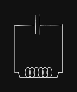
An LC Circuit is a Circuit with a Capacitor and a Inductor.

Here is what happens:
- Initially, we have the left plate of the capacitor with a positive charge, and the right plate with a negative charge.
- Charges move from the positive plate to the negative plate using the wire.
- The Inductor resists the change in current from 0 but around the halfway point, when current should be slowing down to equilibrium, the Inductor resists the slowing down of current and positive charges instead continue to build up on the right plate.
- Now the right plate has positive charge and the left plate has negative charge.
- The process repeats in the other direction, and the charges continue to oscillate between both points.
Lets use Kirchhoff’s Laws to create equations for the circuit:
Note that the equation that we have now looks similar to that of a spring, or simple harmonic oscillator.
The sinusoidal equation for a simple harmonic oscillator looks like:
What we want is to make a sinusoidal equation for the charge oscillation in the circuit by replacing the variables from in the simple harmonic oscillator with the equation we derived from the circuit. We know that
We can differentiate this equation for the Current:
By adjusting the components of the circuit, we adjust
This makes LC Circuits useful for devices to tune into specific frequency, like the radio.
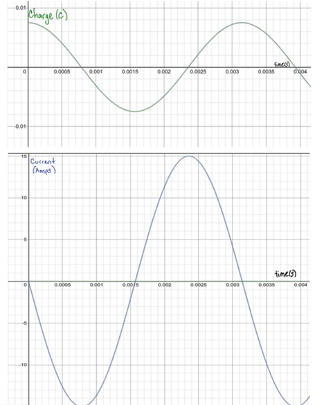
Here are the graphs for charge and current:

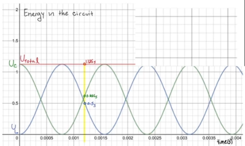
And the graph for energy:
